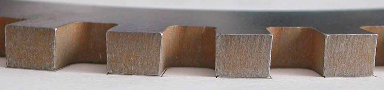
Here is a close-up view of the "teeth" on the trigger wheel. Notice that the cut is not exactly perpendicular to the plane of the triggerwheel. Close enough for this application though.
Here is a close-up view of the "teeth" on the trigger wheel. Notice that the cut is
not exactly perpendicular to the plane of the triggerwheel. Close enough for this application though.
1/4" wood dowels were glued to the pulley to space the triggerwheel at approximately
the center of the space between the pulley and harmonic damper.
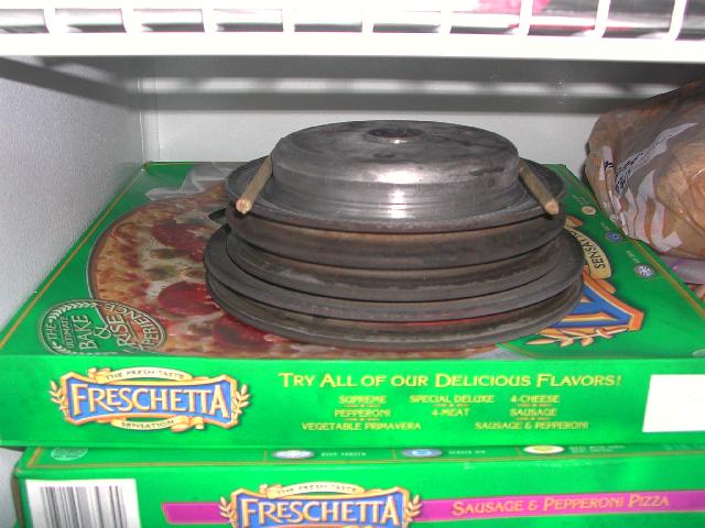
The objective was to expand the triggerwheel with heat and allow it to shrink
into place as it cools, so the pulley was placed in the freezer several hours before
the intallation to shrink it a little.
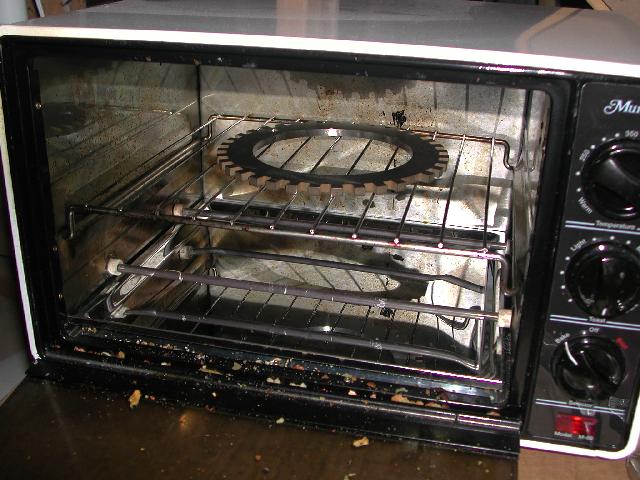
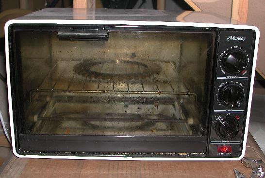
Later the triggerwheel was placed in a toaster oven and "toasted" on high (~500F) for about
20 minutes to make sure it was plenty hot. In a test to see how much the triggerwheel
would grow, a quick measurement showed the inside diameter grew by about 0.010" at 475F.
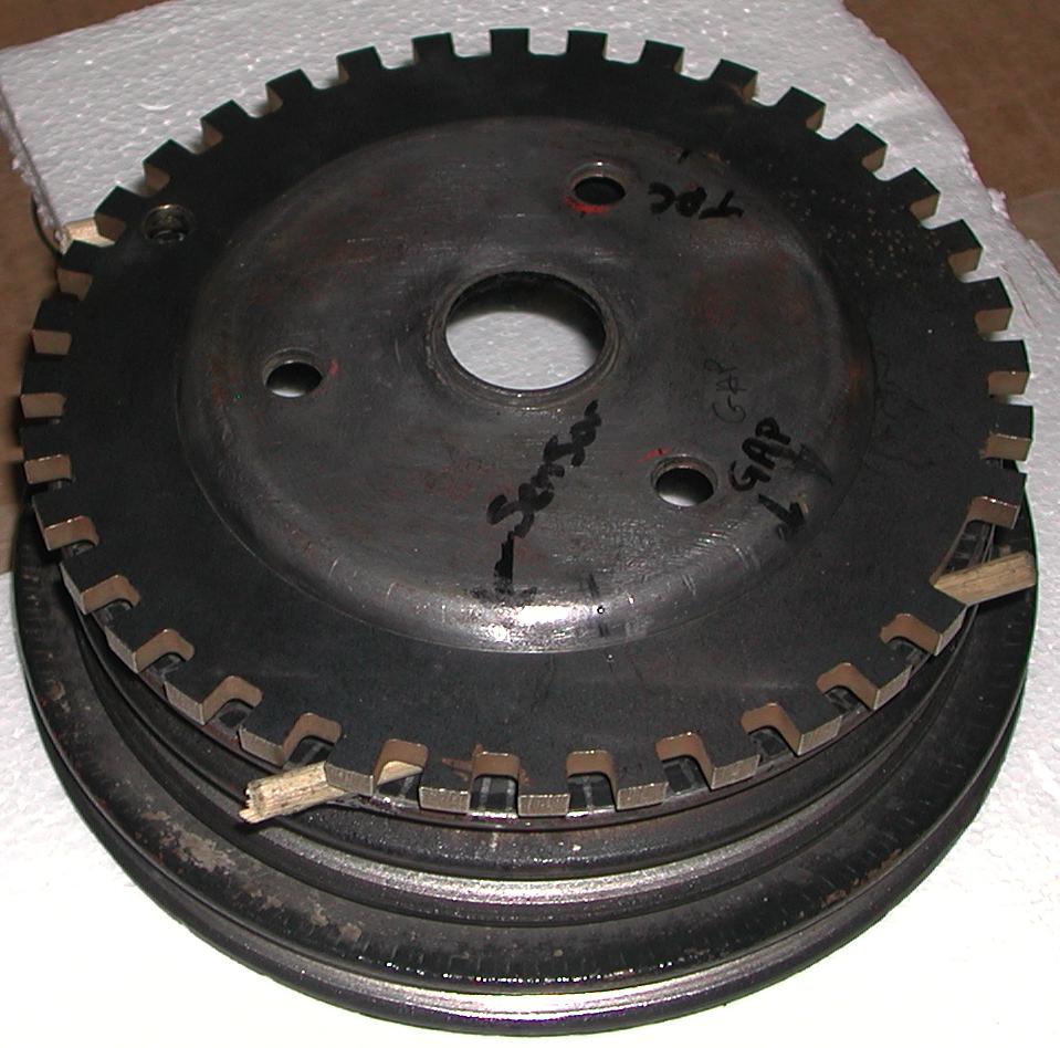
Then the pulley is removed from the freezer and placed on a piece of styrofoam so it
won't warm up too quick. The triggerwheel is then removed from the oven and carefully
placed on the pulley and allowed to cool. Notice the "dots" that I punched on both the
pulley and the triggerwheel that define the desired alignment. The "other" markings are
left-over from the flying magnet arrangement that didn't work as well as I expected. Also
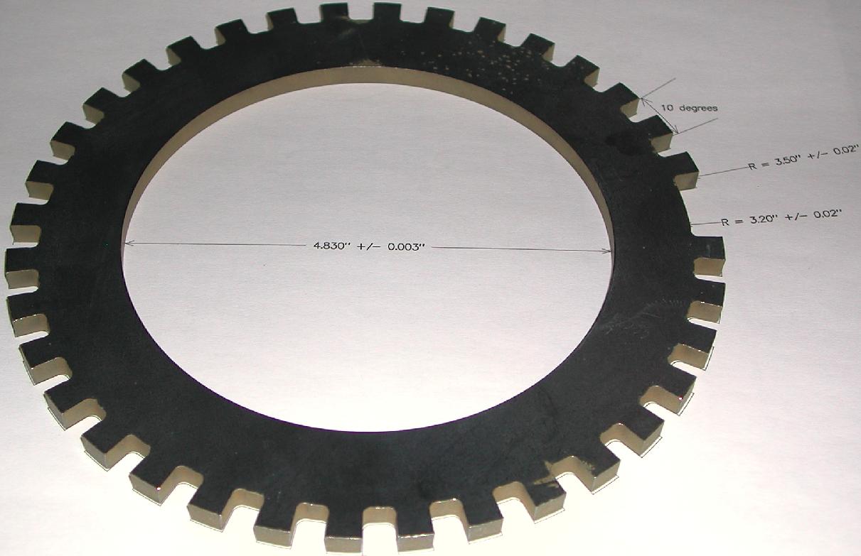
notice the hole I drilled opposite the missing tooth to balance the wheel a little better.
The volume of the hole is slightly larger than the volume of the missing tooth to compensate
for the difference in radial position from the center.
It looks like this when it and the sensor are mounted.
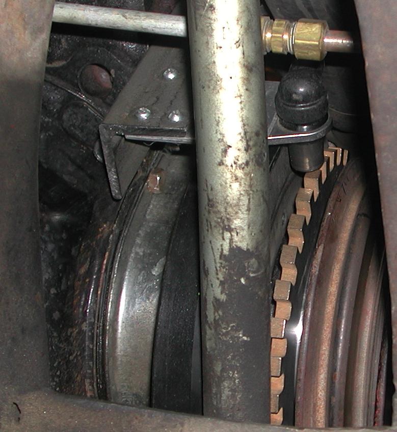
This illustrates the VR sensor position with respect to the missing tooth (assume the crankshaft is at top-dead-center):
The DXF file used to cut this trigger wheel is available here.
I'm very happy with the way it worked out.